Service explanation for JA-110B
Wired glass break detector
This product is part of the JABLOTRON JA-100 alarm system. It is used to detect the breaking of glass panels that form part of the shell of the building to be protected. It responds to air pressure change, which is accompanied by the characteristic sound of glass breaking. The detector has an impulse response (it only reports its own activation). The product is intended for installation by a trained technician with a valid Jablotron certificate.
Installation
The detector is mounted in the interior. There may be no sound/noise sources, no vibrating equipment and/or moving objects that produce a pressure wave in the room to be monitored. We also advise against mounting the detector where air flows (ventilation, air conditioning, draft holes, non-closing doors, etc.). There should be no sound-absorbing objects in front of the detector (e.g. thick curtains).
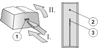
Image: 1 – click clamp of the hood; 2 – sensor; 3 – activation and malfunction signal lights;
1. Open the hood by pressing the click clamp (1)
2. Remove the electronics plate - by loosening the click clamp (5).
3. Pull the cables through the plastic back wall and screw them into place at the chosen location.
Before connecting the BUS, the system must be disconnected from the power supply.
4. Replace the electronics and connect the bus cable to the terminals (6).
5. Follow the installation manual of the control panel. Basic steps:
a. After switching on, the yellow signal light (9) flashes because the detector is not included in the system.
b. In the F-Link program, select the desired position on the Peripherals card and start the learning mode with the Read button.
c. Press the tamper switch in the detector (11) - this will teach the detector and the yellow signal light will go out.
6. Close the detector cover and check that the rubber part of the sensor (4) does not cover the hole in the cover.
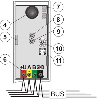
Image: 4 – sensor; 5 – click terminal of electronics; 6 – terminals for the bus; 7 – barcode (placed from below); 8 – red signal light of detector activation; 9 – yellow signal light of the fault; 10 – sensitivity setting; 11 – tamper switch;
Test and set up detector
Hit all glass surfaces in the monitored area in succession with a suitable tool or with a hand in a protective glove (the glass must not break, only deform). The detector responds to the deformation of the glass (change in pressure in the chamber) by briefly flashing the red signal light. The reaction should only come after a clear blow against the glass.
Sensitivity to pressure changes can be adjusted with the trimmer (10). A sensitivity set too high can result in false alarms.
Complex operation of the detector can be checked by the GBT-212 test, which generates the sound of the glass breaking after a blow to the glass. In that case, the red signal light of the detector (8) will light up for 3 seconds.
Turn off signal light
This is done by the F-Link program – card Peripherals. Select the Internal settings at the detector position. A dialog appears in which the detector activation signal light (8) can be turned off.
Detection characteristic
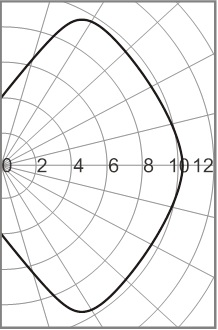
Image: Detection characteristic of the detector.
Technical parameters
Power supply from the central BUS 12 V (9 ... 15 V)
Power consumption in standby (rest) 5 mA
Power consumption for choice of cable 5 mA
Recommended installation height 2.5 m above the floor
Detection distance up to 9 m
Minimum surface of the glass panel 0.6 x 0.6 m
Stabilization period after switching on: max. 60 s
Dimensions 40 x 100 x 22 mm
Classification grade 2
in accordance with CSN EN 50131-1, CSN CLC/TS 50131-2-7-1
Environment according to CSN EN 50131-1 II. inside, general
Working temperature range -10 to +40 °C
Furthermore complies with CSN EN 50130-4, CSN EN 55022
Installation
The detector is mounted in the interior. There may be no sound/noise sources, no vibrating equipment and/or moving objects that produce a pressure wave in the room to be monitored. We also advise against mounting the detector where air flows (ventilation, air conditioning, draft holes, non-closing doors, etc.). There should be no sound-absorbing objects in front of the detector (e.g. thick curtains).
Image: 1 – click clamp of the hood; 2 – sensor; 3 – activation and malfunction signal lights;
1. Open the hood by pressing the click clamp (1)
2. Remove the electronics plate - by loosening the click clamp (5).
3. Pull the cables through the plastic back wall and screw them into place at the chosen location.
Before connecting the BUS, the system must be disconnected from the power supply.
4. Replace the electronics and connect the bus cable to the terminals (6).
5. Follow the installation manual of the control panel. Basic steps:
a. After switching on, the yellow signal light (9) flashes because the detector is not included in the system.
b. In the F-Link program, select the desired position on the Peripherals card and start the learning mode with the Read button.
c. Press the tamper switch in the detector (11) - this will teach the detector and the yellow signal light will go out.
6. Close the detector cover and check that the rubber part of the sensor (4) does not cover the hole in the cover.
Image: 4 – sensor; 5 – click terminal of electronics; 6 – terminals for the bus; 7 – barcode (placed from below); 8 – red signal light of detector activation; 9 – yellow signal light of the fault; 10 – sensitivity setting; 11 – tamper switch;
Test and set up detector
Hit all glass surfaces in the monitored area in succession with a suitable tool or with a hand in a protective glove (the glass must not break, only deform). The detector responds to the deformation of the glass (change in pressure in the chamber) by briefly flashing the red signal light. The reaction should only come after a clear blow against the glass.
Sensitivity to pressure changes can be adjusted with the trimmer (10). A sensitivity set too high can result in false alarms.
Complex operation of the detector can be checked by the GBT-212 test, which generates the sound of the glass breaking after a blow to the glass. In that case, the red signal light of the detector (8) will light up for 3 seconds.
Turn off signal light
This is done by the F-Link program – card Peripherals. Select the Internal settings at the detector position. A dialog appears in which the detector activation signal light (8) can be turned off.
Detection characteristic
Image: Detection characteristic of the detector.
Technical parameters
Power supply from the central BUS 12 V (9 ... 15 V)
Power consumption in standby (rest) 5 mA
Power consumption for choice of cable 5 mA
Recommended installation height 2.5 m above the floor
Detection distance up to 9 m
Minimum surface of the glass panel 0.6 x 0.6 m
Stabilization period after switching on: max. 60 s
Dimensions 40 x 100 x 22 mm
Classification grade 2
in accordance with CSN EN 50131-1, CSN CLC/TS 50131-2-7-1
Environment according to CSN EN 50131-1 II. inside, general
Working temperature range -10 to +40 °C
Furthermore complies with CSN EN 50130-4, CSN EN 55022