Service explanation for JA-110F
Wired water detector
This product is part of the JABLOTRON JA-100 alarm system. The detector serves to indicate flooding in the room to be monitored (basement, bathroom). It responds to the condition (it reports activation, flooding of electrodes and deactivation of the situation, lowering of water level, pumping out of water). The detector is powered directly from the bus cable. The product is intended for installation by a trained technician with a valid Jablotron certificate.
Installation
The detector is intended for flood detection, i.e. it is not designed to remain permanently under water. It is not suitable for overflow detection with an aggressive liquid, e.g. not in a wastewater treatment plant reservoir.
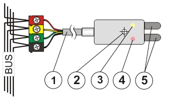
Image: 1 – connection to the bus cable; 2 – mounting hole Ø 3.1 mm; 3 – yellow signal light of the fault; 4 – red activation signal light; 5 – detection electrodes
1. Choose a suitable location for mounting the detector and also a suitable location for the bus cable terminals or the JA-110T bus isolation, if required. The JA-190PL box for electrical installations can be used to install the connection to the bus.
2. Connect the bus cable (1) to the terminals.
Before connecting the BUS, the system must be disconnected from the power supply.
When the module is placed outside the room to be monitored, the BUS supply must be separated from the bus by the JA-110T.
3. Follow the installation manual of the control panel. Basic steps:
a. After switching on, the yellow signal light (3) flashes because the detector is not included in the system.
b. In the F-Link program, select the desired position on the Peripherals card and start the learning mode with the Read button.
c. Briefly connect the detection electrodes (5) - this will cause the detector to learn and the yellow signal light (3) will go out. Tip – connect the electrodes to each other with a damp finger.
Set detector properties
This is done by the F-Link program – card Peripherals. Select the Internal settings at the detector position. A dialog will appear in which you can set:
Delay of reaction to entry: time filter to improve immunity against false activation – setting of 0.5 sec ... 300 sec determines how long the detection electrodes must be connected before the control panel activates the activation.
Reverse reaction of running-in: (inversion) The factory setting is that the system responds to electrode continuity (flooding). One can also choose the opposite reaction.
LED indication during communication: allows you to turn off the red signal light that indicates both activation and deactivation of the detector by flashing once. In service mode the indication is always active.
Indication of alarm: When switched on, the red signal light (4) indicates the flooding by flashing twice briefly, even after the water level has dropped, if the electrodes are no longer connected. The flashing remains on until the indication is canceled by the control panel (arm again, switch off in the menu or start of the service).
Technical parameters
Power supply from the BUS of the central unit 12 V (9…15 V)
Power consumption on standby 5 mA
Power consumption for choice of cable 5 mA
Detector responds to water flooding
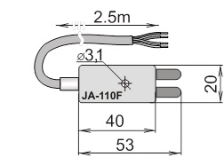
Dimensions 53 x 20 x 10 mm
Environment according to CSN EN 50131-1 II. inside, general
Working temperature range -10 to + 40 °C
Furthermore complies with CSN EN 50130-4, CSN EN 55022
Installation
The detector is intended for flood detection, i.e. it is not designed to remain permanently under water. It is not suitable for overflow detection with an aggressive liquid, e.g. not in a wastewater treatment plant reservoir.
Image: 1 – connection to the bus cable; 2 – mounting hole Ø 3.1 mm; 3 – yellow signal light of the fault; 4 – red activation signal light; 5 – detection electrodes
1. Choose a suitable location for mounting the detector and also a suitable location for the bus cable terminals or the JA-110T bus isolation, if required. The JA-190PL box for electrical installations can be used to install the connection to the bus.
2. Connect the bus cable (1) to the terminals.
Before connecting the BUS, the system must be disconnected from the power supply.
When the module is placed outside the room to be monitored, the BUS supply must be separated from the bus by the JA-110T.
3. Follow the installation manual of the control panel. Basic steps:
a. After switching on, the yellow signal light (3) flashes because the detector is not included in the system.
b. In the F-Link program, select the desired position on the Peripherals card and start the learning mode with the Read button.
c. Briefly connect the detection electrodes (5) - this will cause the detector to learn and the yellow signal light (3) will go out. Tip – connect the electrodes to each other with a damp finger.
Set detector properties
This is done by the F-Link program – card Peripherals. Select the Internal settings at the detector position. A dialog will appear in which you can set:
Delay of reaction to entry: time filter to improve immunity against false activation – setting of 0.5 sec ... 300 sec determines how long the detection electrodes must be connected before the control panel activates the activation.
Reverse reaction of running-in: (inversion) The factory setting is that the system responds to electrode continuity (flooding). One can also choose the opposite reaction.
LED indication during communication: allows you to turn off the red signal light that indicates both activation and deactivation of the detector by flashing once. In service mode the indication is always active.
Indication of alarm: When switched on, the red signal light (4) indicates the flooding by flashing twice briefly, even after the water level has dropped, if the electrodes are no longer connected. The flashing remains on until the indication is canceled by the control panel (arm again, switch off in the menu or start of the service).
Technical parameters
Power supply from the BUS of the central unit 12 V (9…15 V)
Power consumption on standby 5 mA
Power consumption for choice of cable 5 mA
Detector responds to water flooding
Dimensions 53 x 20 x 10 mm
Environment according to CSN EN 50131-1 II. inside, general
Working temperature range -10 to + 40 °C
Furthermore complies with CSN EN 50130-4, CSN EN 55022