Service explanation for JA-180G
Gas leak detector
The JA-180G detector ensures the timely detection of leakage of flammable gases (natural gas, light gas, propane, butane) and flammable vapors. The detector is operated directly from the el. mains powered, signals gas leakage optically and acoustically and also transmits information via Jablotron radio protocol.Installation
The detector is intended for installation in areas without significant hazard - e.g. residential buildings, light industrial areas or boiler houses.
We recommend that the installation be carried out in accordance with EN 50244 and by a person with the required electrical qualification!
Open the detector screen by pressing the click clamp on the side and attach the rear part of the housing with the electronics panel using. screws in the chosen location. Install the detector for lighter-than-air gases (natural gas) near the location, above the possible leakage of the gas, on the wall, maximum 15 cm below the ceiling or directly on the ceiling. Install the heavier-than-air gas (propane) detector close to the floor or at the lowest point of the room/room. Always position the detector so that the entrance and exit openings in the detector screen face the assumed direction of airflow.
Never install the detector near obstacles that hinder natural air circulation, in places where there is a shortage of oxygen and in places where the operation of the detector may be affected by various odors (stench) or by vapor condensation (e.g. near a stove). A strong air flow in the vicinity of the detector can also have a negative effect on detection.
Connect the supply conductors, set the internal switches, close the detector screen, enable the control panel (receiver) learning mode and finally switch on the detector power supply.
Power supply terminals
Power supply from the electricity grid is connected to the terminals marked 230V AC. The connection is via a fixed supply cable. Before turning on the power, check the connection and close the detector screen. Never open the detector with the power on.
Terminals of the relay
Switch contacts of the output relay are routed to the terminals as follows:
C common contact
NO make contact
NC normally open contact
The output of the relay can be used for automatic blocking of gas supply via an electric valve, for external signaling of danger, and the like.
NOTE: The mains output of the relay does not cause a safety break!
Internal switches
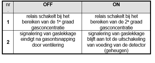
There are two adjustment switches in the detector:
no. OFF ON
1 relay switches when the 1st degree gas concentration is reached, relay switches when the 2nd degree gas concentration is reached
2 gas leakage signaling ends after gas escape through ventilation gas leakage signaling remains on until the detector power supply (memory) is switched off
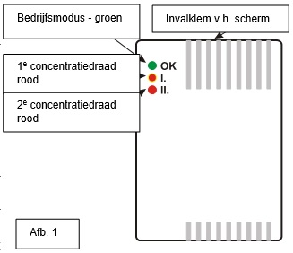
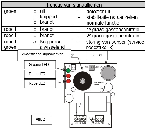
Function
After switching on the power, the detector sends a learning signal to the central unit (receiver) and the green signal light starts flashing (for approx. 90 sec. - detector is stabilizing). Then a short beep sounds and the green light remains on continuously, which means that the sensor is ready to work.
When the concentration of the leaking gas reaches the value of the 1st degree sensitivity, short audio signals sound and the red light I. lights up.
If the gas concentration exceeds the 2nd degree sensitivity, long audio signals will sound and the red light II will sound. lights up.
The fact at which gas concentration the relay will respond is determined by internal switch no. 1.
The alarm signal (Fire type) is sent by the detector at the moment of relay activation (i.e. the transmission is influenced by the setting of internal switch no.1).
The JA-180G detector does not check the connection to the control panel (receiver), i.e. the system does not report a loss of detector in the event of a power failure of the detector.
PLEASE NOTE – if a gas leak is indicated, prevent fire (ignition) in this room (do not use electrical switches, ventilate thoroughly, stop gas leakage, call the fire brigade or gas supplier if necessary).
Maintenance and informative function check
Keep the device clean and occasionally check whether the grille of the lid is permeable and, if necessary, clean it by carefully blowing away the dust.
Detector response can be tested using a gas cigarette lighter (without flame). The expert calibration of the detector is carried out by the manufacturer and is recommended at least 1 year after commissioning.
Technical parameters
Power supply from the mains 230V (+10 to -15%) / 50Hz, approx. 2W, available. class II
Loud alarm 94 dB / 0.3 m
Relay output optional response to 1st or 2nd degree
Load capacity relay switching contact max. 230 V / 5 A
Working temperature -10 °C to +40 °C
Relative humidity 25 to 75%
Warm-up time after switching on approx. 90 s
Response time up to 10 s
Method of detection catalytic oxidation
Security IP 30 (EN 60 529)
Communication band 868.1MHz, Jablotron protocol
Communication range approx. 200m on direct visibility
Dimensions, weight 101 x 74 x 39, 210 g
Constructed for operation in normal atmospheric pressure i.e. 86 to 106kPa
Complies with EN 61779-1, EN 61779-4, EN 50130-4, EN 55022, ETSI EN 300220, 60950-1
Intended for environments without significant hazard BE 1 (2000-3)
Sensitivity:
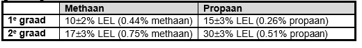
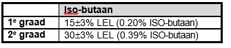
Note: O.E.G. = lower explosive limit, calibrated by iso-butane
The product has been designed and manufactured in accordance with the provisions applicable to it: Government Decree No. 426/2000 Coll., provided it is used according to its intended purpose.
Note: Although this product does not contain harmful materials, do not dispose of it in the household waste, but hand it in at the collection point intended for electronic waste.