
Service explanation for JA-80Q
1 Installation in the control panel
Important: Hardware compatibility with the JA-80K control panel is from hardware version KE10104. Check the description on the main board of the control panel. (the version number is printed right next to the RESET jumper.)
If you purchased the module separately, it must be installed in the Oasis control panel as follows:
1. The central unit must be completely disconnected from electricity (both 230V and the battery)
2. Plug the JA-80Q module (in the control panel) into the digital bus connector designed for the (standard) JA-80Y connection
3. For parallel use of a JA-80Y module, insert the plug of the dialer into the socket of the JA-80Q module.
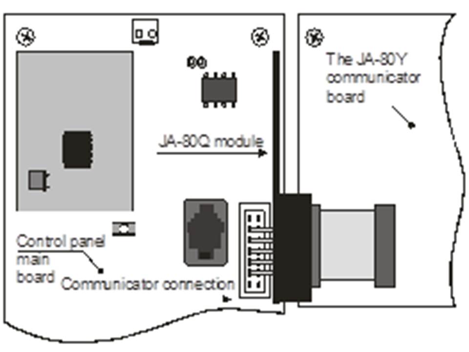
2 Learn detectors with camera
Installation may only be performed by a certified technician approved by an authorized distributor.
1. Place the central unit in service mode and press the 1 key on the control panel to activate the learning mode (see description of the central unit).
2. Learn the JA-84P by inserting its battery (see description of the JA-80P)
3. Exit the central unit's enrollment mode.
Note: If the detector was already enrolled in the control panel before the JA-80Q module was installed, you do not need to re-learn the detector. You only have to activate the learning mode and exit again. In this way the module will obtain all relevant information from the control panel
3 Programming the dialer
For successful transmission to the web server that has a photo receiver program, the server IP address must be programmed into the JA-80Y or JA-80V dialer. The address of the Jablotron photo display website is http://img.jablotron.com.
IP address is: 77.104.20.129 port 7070
1. Place the control panel in service mode.
2. Program the required IP address and port to be used to send the data to with the ComLink program (in the ARC window) or by entering the following sequence.
013 *8 xxx xxx xxx xxx yyyyy *0
Where:
xx..x is the 12 digit IP address
y..y is the 5 digit port number of the receiver. See also the description of the voter.
Example: 013 *8 077.104.220.129 07070 *0
3. Exit the control panel's service mode.
Important:
The setting or change to the setting is only active when the control panel is taken out of service mode.
The information about a new photo via SMS is sent to all telephone numbers that also receive the event "burglary alarm – immediately". This SMS also contains a link to the new photo on the server. This option is available on the JA-80Y from software version number XA61009 and on the JA-80V from software version number XA64005.
4 LED signals
After taking a photo of a detector, the photo will be sent to the control panel and then to the JA-80Q module via the digital bus. This is indicated by a green flashing LED. Successful transmission is confirmed by a long green flash (2 sec). Failed transmission is indicated by a series of rapid green flashes at the end.
Once the photo has been received by the JA-80Q module, the photo is sent via the dialer to the pre-programmed web server. This transmission is indicated by a flashing red LED on the JA-80Q module. Successful transmission is confirmed by a long red flash (2 sec). Failed transmission is indicated by a series of rapid red flashes at the end.
The total time taken from the moment the photo is taken until it is received on the web server is approximately 20 seconds. With a weak signal, delays may occur (because the data is sent multiple times). Each photo has a date and time indication (copied from the control panel) when it was taken. It takes at least 60 minutes from the moment of connection before the time of the photos is synchronized with the central unit.