
Service explanation for JA-81M
1 Installation
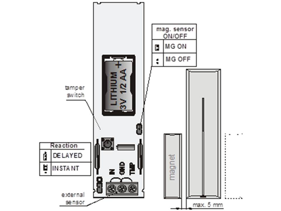
Installation may only be performed by a certified technician approved by an authorized distributor.
This detector responds when its magnet is removed. The detector should be placed on the non-moving part of a door or window, and the magnet on the movable part. The detector must be placed vertically. Avoid placing on metal parts that could disturb the magnetic properties and/or the radio signal. If the door or window is made of metal, we recommend hanging the detector somewhere else and connecting a wired magnetic contact to the detector.
See the following instructions:
1. Open the housing by pressing the tab at the bottom.
2. Screw the back onto a non-movable part from the door or window.
3. Attach the magnet to the movable part of the door or window. The distance to the detector should not exceed 5mm when the door or window is closed. The bottom of the detector should be flush with the bottom of the magnet. Only one magnet can be placed, this can be on the left or right of the detector.
4. Do not insert the battery yet and leave the housing open. Follow the manual of the control panel or receiver.
The basic method for learning is as follows:
1. Activate the learn mode by pressing "1" in the service mode.
2. Insert the battery into the detector to register the detector.
3. Exit the enrollment mode by pressing "#".
To register the detector if the battery has already been installed; Remove the battery and then press the tamper switch several times to remove residual voltage.
2 DIP switches
MW ON / MW OFF This allows the internal magnetic contact disabled if only an external sensor is connected.
INS v DEL With INS an alarm will be generated immediately when the detector is activated, DEL will start the input delay when the control panel is armed. The DIP switch (INS/DEL) only has effect if the detector in the Oasis control panel is set to neutral response.
It has no effect if the detector is used with a UC-8X or an AC-8X receiver. Opening the housing will result in a tamper message.
3 Open/close status detection
The factory setting of the detector allows it to report both the opening and closing of a door or window to the central unit. If you want only the opening of a door or window to be reported, press and hold the tamper switch when the battery is inserted.
4 Connecting external sensor
External sensors can be connected to the detector. It is possible to protect multiple doors or windows or to connect other wired detectors. There are 2 entrances, IN and TMP which will respond when disconnected from the community GND connection
IN: If the IN connection is disconnected from the GND connection, the detector will be the same signal send to the center as if its own magnet were removed of the detector. The internal sensor can be disabled using the DIP switch if desired is.
TMP: The TMP connection will send a tamper signal when it is disconnected from the GND connection.
Please note: If one of the two inputs is not used, it must be short-circuited to the GND connection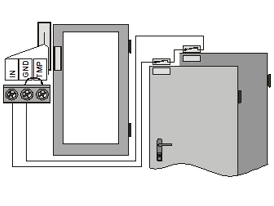
5 Testing the detector
Up to 15 minutes after closing the housing, the LED indicator will light up when the door or window is opened or closed. The signal strength can be measured by the control panel in Service mode.
6 Replace battery
The detector monitors the battery voltage. If this becomes too low, the detector will send a signal to the control panel to warn the user or technician. The detector will continue to operate and the LED will flash each time the detector is activated. Battery replacement should not be delayed longer than 2 weeks. Replacement must be done by a certified installer when the control panel is in Service mode.
Do not just throw away empty batteries, follow the local rules for disposing of batteries.
7 Removing the detector from the system
If the detector needs to be removed, first remove it from the control panel and then remove the detector.
8 Technical parameters
| Voltage: | Lithium battery type CR14250SL (1/2 AA 3.0V) |
| Normal battery life: | About 3 years with max. 20 activations per day |
| Communication band: | 868 MHz, Oasis protocol |
| Range: | Approximately. 300m (open field) |
| Normal detection range of the internal sensor: | 45/25mm |
| Dimensions: | 110 x 31 x 26 mm |
Inputs for external sensors IN and TMP = normally closed loops