
12.34 Panic alarm with sound
When activated, the panic alarm can be indicated by the sounding of the sirens (sirens on IW and EW):
6 9 3 0 silent panic alarm
6 9 3 1 panic alarm with siren sound
Note: When code 370 is used the panic alarm will be a silent panic alarm when one or more sections of the system are unarmed.
Factory setting: silent panic alarm
12.35 Higher sensitivity of the control panel
When activated, this function will increase the radio range between the control panel and the wireless items provided there is no radio frequency interference in the building.
6 9 4 0 standard sensitivity of the control panel
6 9 4 1 higher sensitivity of the control panel
Note: The sensitivity of the control panel should only be increased when there is no RF interference, otherwise increasing the sensitivity will result in a smaller range than before!
Factory setting: standard sensitivity of the control panel
12.36 Access via code + card
This function increases the security against unauthorized arming or disarming of the system
6950 access by code OR card
6951 access by code AND card, both must be assigned to the same user, so to 1 address!
Notes:
· The system has up to 50 user addresses (01 to 50). A user code and access card can be programmed at each address. If both a card and a code are assigned to 1 user, the above code will indicate that the user must either enter both to operate the system, or enter 1 of the two. The order code and/or card is in no way important.
· When only a card or a code is assigned to a user, the above code does not affect the operation
Factory setting: system access by code or card
12.37 24 hour alarm with siren sound
The 24h burglar alarm which can be triggered when the system is armed or not, can also be either a silent alarm or an alarm with siren triggering (IW and EW) using the following codes:
6 9 6 0 silent 24-hour burglar alarm
6 9 6 1 24-hour burglar alarm with siren sound
Note: When code 370 is used the panic alarm will be a silent panic alarm when one or more sections of the system are unarmed.
Factory setting: 24-hour burglar alarm with siren sound
12.38 Access to service mode only possible with service code and "Master" code
To prevent the installer from entering the service mode without permission from the user, if the function below is activated, the service mode can only be accessed if the master code or user code is entered immediately after the service code. To enter the service mode you must enter *0 service code master code (or user code)
6 9 7 0 Only the service code is sufficient
6 9 7 1 service code and master code required.
Factory setting: Only the service code is sufficient
12.39 Reactions of the items and assignment of partitions
With the following code you can determine the characteristics of the system items: 61 nn r s
Where:
nn is an element from zone 01 to 50 (01 and 02 can be either a hard-wired detector or a wirelessly read detector)
r the response code from 0 to 8 – see table 2
s section (partition) 1 = A, 2 = B, 3 = C (only has an effect when partial reinforcement or a split system is applied)
· With partial arming, detectors can be assigned to different sections: A (s=1), B (s=2) and C (s=3). You can divide the 3 different options as follows:
A Press the A key on the keypad, for example to arm the garage in the afternoon
AB Press the AB key on the keypad, for example to arm the garage and the ground floor at night.
ABC Press the ABC key on the keypad, for example to arm the entire system when leaving the house
· In a shared "split" system, detectors can be assigned to sections: A (s=1), B (s=2) a C (s=3). Sections A and B can be armed and disarmed separately, section C is a common section that will only arm if both section A and section B are armed.
Partially arming or sharing a system only has a useful effect on intrusion detectors with immediate, delayed or subsequent delay responses. Detectors with fire, tamper, panic and 24h responses are always ready to trigger an alarm, regardless of which section these detectors are assigned to, and regardless of the system status, armed or unarmed.
· If you have taken PG output control in response, the S factor determines which PG output is controlled: S=1: PGX, S=2: PGY and S=3: PGX&PGY
Programming responses:
· The reaction you select in a detector via the dip switches will only be accepted by the control panel if the reaction in the control panel is set as a natural reaction. (r=1)
· Remote control buttons will always be read in pairs into the central unit ( +
+ ) or (
 +
+ )
)
If a different response is selected for a remote control, this response will only apply to the first pair of buttons, i.e. or , with the exception of the PG outputs.
Factory setting: All devices have a natural response (r=1) and are assigned to section C (s=3).
12.40 Code/map responses and partition assignment
With the following code you can assign the response and partition to access code and cards: 62 nn r s
Where:
nn is the user position from 01 to 50
r is the response index from 0 to 8 – see table 2
s is the section 1 = A, 2 = B, 3 = C (Only has an effect in a shared "split" system – except for PG output responses)
Assigning codes and cards to sections:
With partial arming: Assigning codes or cards to sections has no effect (except for the PG output control response). When a partition in the system is armed, and a code or card is used, the system will disarm, when all partitions are disarmed, the entire system will be armed with a code or card. The A and B buttons for partial arming can optionally be followed by a valid code before arming/disarming. (see setting chapter 12.13)
For a shared system, a code assigned to a section:
A control section A
B control section B
C control section A, B and C.
If the system is not shared, assigning codes and cards to sections will have no effect, but the s parameter must still be entered in the programming. Give S=3 for a non-shared system
Code/card responses:
· When a code/card has a natural response (r=1), its response is arm/disarm/arm... (same as response r=9)
· An alarm response can also be given to a code/card, the same as with detectors
Factory setting: all codes/cards from 01 to 50 have a natural reaction (arm/disarm) and are assigned to section C.
12.41 Reading items via the factory code
The following code allows the reading of devices via production codes: 60 nn xx..x
Where:
nn the address of the element from 01 to 50
xx...x the production code of the device, the last 8 digits of the barcode can be found on the label inside the device.
Notes:
· If address nn has already been assigned, the current device will be deleted and the new device will take its place.
· If a device with production code xx..x has already been read at a different address, and it is now read again at a new address, this device will be moved to the new address, whereby the previous address will be released again.
· If you enter nn=01 or 02, the device will be read at these addresses that are in principle provided for hard-wired inputs, these wired inputs are then inactive.
· If a 0 is entered 8 times as a production code, the device assigned to the address in question will be deleted.
12.42 Automatic arming/disarming via daily schedule
This can be used to set an automatic daily arm/disarm sequence. Up to 10 daily events can be programmed, which will repeat every day of the week: 64 n a hh mm
Where:
n event number from 0 to 9
a event type 0 to 6 (see table below)
hh hours (event time)
mm minutes (event time)
* same event on a non-shared system
** only possible with partial reinforcement
Notes:
· The automatic arming and disarming schedule can also be programmed in maintenance mode.
· When the automatic schedule is not used for arming/disarming and the system is not shared, it can also be programmed as a daily timer to switch a device connected to the PGY output of the control panel. To do this, make the system a shared system and ensure that no detectors are read into section B. (Keep this section empty). Then program the PGY output to be triggered when arming section B and then program the automatic arming schedule. (with a=4) to arm/disarm the empty section B which then switches the PGY output on and off according to the set schedule.
Factory setting: No schedule is set
12.43 Changing the service code
The service code can be changed with the following code: 5 NC NC
Where:
NC = new code (4 characters), the new code must be entered twice in succession.
Example: the code 1276 can be programmed by code: 5 1276 1276
Factory setting: 8080
12.44 Go to maintenance mode
When entering code 292 in service mode, the system will switch to maintenance mode. In maintenance mode it is possible to bypass devices and change the internal clock (see 13.4)
12.45 Setting the internal clock
The control panel has a built-in real-time clock that is used to provide the correct date and time for events stored in the control panel's memory. You can adjust the clock with the following code: 4 hh mm DD MM YY
Where:
hh the time in hours (00 to 23)
mm the time in minutes (00 to 59)
DD the day (01 to 31)
MM the month (01 to 12)
YY the year (00 to 99)
12.46 Change keypad texts
The names of devices and programmable outputs displayed on the LCD keypad can be changed by the following procedure:
· Keep the ? key pressed (in service mode), in the displayed menu you see the name of the imported element at address 01 while the cursor flashes on the first character.
· Key functions: and
and  scrolling text
1 and 7 selection character (A,B,C,D......8,9,0)
4 and 5 cursor control (left/right)
2 delete selected character
# exit menu (& save settings)
List of adjustable texts:
0 to 50: Devices - Names of items from address 01 to 50
Control panel - Name of the control panel
Keypad - Name of the wired keypad
Voter - Name of the voter at the exchange
Master code - Name of the master code
01to 50: Code - Name of the user codes
Service code - Name of the service code
PGX and PGY - Name of the programmable outputs
OASIS JA-80 - The default text during normal operation when no other texts should be displayed.
Notes:
· Only capital letters can be entered.
· The length of the text is limited according to the number of characters on the LCD screen
· The text is only stored in the connected keypad for storage, it is possible to program different texts per keypad if desired.
· Texts are stored in the keypad's memory, they are not deleted in the event of a power failure.
· User-friendly text editing is possible via the comlink software.
· In addition to names of the items, the keypad also has internal texts such as "service", "maintenance mode" etc... This text can also be entered via the Comlink software via the menu "settings" and then the submenu "keypad texts"
· After entering the texts via the Comlink software, all keypads (also type JA-80F) must be connected to the bus for the transfer of the texts to the keypad, press ok in the menu and the texts are automatically saved in the keypad.
Factory setting: in addresses 01 to 50 you see the text "Device". Other texts: "Control panel", "Keypad", "Communicator", "Master code", users 01 to 50 "Code", "Service code", "PGX", "PGY" and "OASIS JA-80".
13 Operating the system
The OASIS system can be operated locally using the keypad, a remote control or remotely via telephone or via the internet or via PC with the comlink software.
13.1 The system keypad
Inside keypads model JA-80F (wireless) or JA-80E (wired) can be used to operate the system and to program the system. Both keypad types offer the same functions: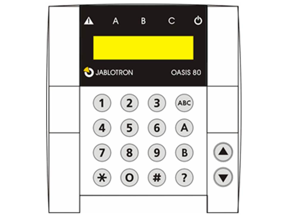
*6 access code/card programming (*6 MC nn NC)
*7 for operation while under duress (should be entered before the access code to secretly signal distress)
*8 PGX control (ON/OFF = *81/*80 or *8 to be triggered when a pulse response is programmed)*
*9 PGY control (ON/OFF = *91/*90 or *9 to be triggered when a pulse response is programmed)*
*0 To Service Mode (*0 SC – factory setting 8080) or maintenance mode (*0 MC – factory setting 1234)
The * key allows the system to be controlled via a mobile telephone (if the control panel is equipped with a dialer)
13.1.1 Keypad LED indication
ABC arming status of sections – when all sections are armed, indicators A,B and C are illuminated red.
flashing = alarm, with the alarm displays on the LCD screen, e.g.: Alarm 03: Kitchen
continuously lit = error – details of the error can be displayed by pressing the ? test
Tension. Continuously illuminated = voltage ok. Flashing = no voltage, the control panel is powered by the backup battery
13.1.2 LCD screen
The first line shows the status: triggered detector, Service mode, etc... In standby mode you see the text "OASIS JA-80" (can be changed see 12.46)
The second line shows the name of a zone (e.g. 01: main entrance etc.). See Error! Reference source not found..
Showing the status of detectors and programmable outputs: Details of permanently triggered detectors (e.g. open window) and the status of the PGX and PGY outputs can be displayed by pressing the ? button.
13.1.3 Sleep mode of the keypad screen
In normal operating mode, the JA-80F wireless keypad will display the system status for 20 seconds (when powered by batteries) after the last interaction and then enter sleep mode. When pressing a key or opening the cover, the keypad will become active again and display the status.
13.1.4 Tests
Enter 0–9 digital code
* Function sequence
# Exit menu
ABC hotkey for full arming (all sections A, B & C)
A shortcut key for arming section A (e.g. partially arming garage)
B in a non-shared "unsplit" system: shortcut key for arming sections A and B (e.g. partial arming of the first floor and the garage).
In a shared "split" system: hotkey for arming section B (C is only armed if sections A and B are armed)
? Showing triggered detectors (e.g. open windows), faults and details and PGX / PGY status. Activating the PGX output via the keypad (same effect as function *81) Activating the PGY output via the keypad (same effect as function *80)
Notes:
· The A and B buttons only have a function when partial arming or parts of the system are activated.
· The arrow keys only control the PG outputs if this is programmed -> see 12.5.
13.1.5 Functions via * key
The following functions are available to the user via the keypad:
*1 fully arm (same as ABC key)*
*2 arm section A (same as key A)*
*3 arms A and B, or only B (same as key B)*
*4 call memory (key 4 scroll back) – the last 255 events are stored in the control panel
*5 new Master Code/Card (*5 MC NC NC)
*6 access code/card programming (*6 MC nn NC)
*7 for operation while under duress (should be entered before the access code to secretly signal distress)
*8 PGX control (ON/OFF = *81/*80 or *8 to be triggered when a pulse response is programmed)*
*9 PGY control (ON/OFF = *91/*90 or *9 to be triggered when a pulse response is programmed)*
*0 To Service Mode (*0 SC – factory setting 8080) or maintenance mode (*0 MC – factory setting 1234)
The * key allows the system to be controlled via a mobile telephone (if the control panel is equipped with a dialer)
13.2 Programming Access Codes and Cards
Access to the system is possible via 4-character access codes or via access cards or tags (PC-01 or PC-02) EM technology 125kHz )
· The control panel has 1 service code, 1 master code and 50 user codes.
· The service code can only be a numerical code of 4 characters. (factory setting is 8080)
· The master code can be either a numeric code (factory setting 1234) or an access card. Other users can be created or deleted using the master code/card.
· Each user from 01 to 50 can have a numeric code, a card, or both.
· Factory setting, all user codes or cards are erased
· If a user has both a code and a card, you can indicate whether both or one of them is needed to operate the system (see 12.36)
· It is not possible to assign the same card or code to multiple users. If you want to assign a code or card to another user, you must first delete the code or card from the current user.
· It is possible to display the programmed cards and codes on the keypad in maintenance mode (See 13.4.1)
· The control panel will accept 10 invalid (unsuccessful) attempts to enter a valid code or card. From the 11th attempt a tamper alarm will start.
13.2.1 Programming access codes and cards
Not available
13.3 Arming and disarming the system
The system can be armed and disarmed using the keypad, a remote control or remotely via telephone or via the internet or via PC with the comlink software.
Arming the system with a keypad:
· Press button ABC, A or B,
· Enter your code or present the access card.
· If the system is partially armed (eg section A), and you want to arm multiple sections, press B or ABC.
When you expand an armed section with an additional section, all delayed and subsequent delayed detectors in these sections will be armed, and in the section that are already armed an exit delay will be activated. If a user wants to arm an additional section, he can leave the building via the sections that were previously armed. The user does not therefore have to first disarm the entire system and then re-arm the entire system before leaving the home. The user's chosen path to exit the building must include delayed or subsequent delayed detectors. This must therefore be taken into account when designing the system.
To disarm via a keypad:
· Enter a valid access code (or present the access card)
Operate the system with the JA-80H outdoor keypad
If the system is equipped with an outdoor keypad (JA-80H) or a JA-80N external card reader, the outdoor keypad can either operate in the same way as the indoor keypad (JA-81F or JA81E) or it can be programmed to only control the electric lock. E.g. An indoor keypad can be used to operate the alarm system and if the outdoor bypass function is activated you have the following settings:
· Arming and disarming is only possible via remote control or via indoor keypad JA-81F or JA-81E.
· Pressing a valid access code or card will only open the electric lock.
· If the system is armed and the door is opened, an entry delay will start when entering the building. During the delay, the system must be disarmed via the indoor keypad JA-81F or JA-81E.
13.4 Maintenance mode
To enter maintenance mode, enter the following code: *0 MC
Where:
MC is either the master code or the master card.
In maintenance mode it is possible to:
· Items to test (an alarm cannot be triggered),
· Displays of which card and code position are occupied.
· Bypassing individual zones (for 1 arm/disarm cycle or definitive) see 13.4.2
· Programming the internal clock see chapter Error! Reference source not found..
· Programming the automatic arm/disarm schedule - seeError! Reference source not found..
· Programming telephone numbers for event reporting (see Error! Reference source not found.).
· Exit maintenance mode by pressing the # key
13.4.1 Display of the programmed codes and cards
The programmed codes and cards in addresses 01 to 50 can be displayed as follows:
1. The control panel must be in maintenance mode, if not, enter *0 Master code (factory setting 1234), in unarmed condition.
2. Press 5 (the screen will show "Codes 01: Code"),
3. Use the arrow keys to scroll through the different positions (01 to 50), the A LED will light up when a code has been read and the B LED will light up when cards have been read in.
4. Press # to leave the menu
5. Press # again to exit maintenance mode
To change access code or cards, press *6 MC nn NC (see Error! Referral source not found.).
The Comlink software allows you to easily display the list of occupied codes and cards, where the codes are readable and therefore secret.
13.4.2 Bypassing items
It is possible to bypass certain items in maintenance mode, either permanently or only during arming/disarming.
1. Place the control panel in maintenance mode via *0 master code (factory setting: 1234) when the system is not armed.
2. Press key 1 to see the Bypass menu on the keypad.
3. Use the arrow keys to scroll through the different items that can trigger an alarm
4. To bypass a zone, use the following keys:
Press 2 to bypass the zone for 1 arm and disarm cycle (the triangle LED will start flashing)
Press 3 to permanently bypass a zone (the triangle LED will light continuously)
To cancel bypassing a zone, use the same key you used to bypass that zone (key 2 or 3). Using key 4 will cancel bypass for all zones in the system.
5. Bypassing the desired zones can be done by repeating steps 3 and 4.
6. To exit the bypass menu, press #, press # again to exit the maintenance menu.
When a system with bypass programmed zones is armed, the bypass texts will be displayed on the keypad.
13.4.3 Securing a vehicle in the vicinity of the system
The OASIS system can also protect a car parked nearby within radio range of the system.
1. If the car has a built-in car alarm, an RC-85 transmitter can be connected to the output of the car alarm, the RC-85 module can be read into a free zone in the central unit. If the car alarm triggers an alarm, this can be programmed as a panic alarm, 24 hours a day, even if the system is not armed.
Note: When the vehicle alarm confirms arming by siren sounds on the alarm output, it must be disabled to avoid false alarms.
2. If there is no built-in car alarm, the JA-85P and JA-85B detectors can be installed in the car. You can give these detectors their own partition in the system, for example with a split system you can use partition A for the weapon detectors and partition B for the home, where zone C is not used, and the codes and cards assigned to section C can operate the entire system. When the user arrives home, he can disarm section B to enter the house, and arm section A to secure the car. It is best to switch off the radio communication supervision for the weapon detectors to avoid false error messages when the car drives away from the house.
14 Operating and programming the system via PC
The Oasis system can be operated and programmed via your PC using the Comlink Software. Connect the control panel to the PC with the JA-80T interface or via the JA-80TB Bluetooth interface.
The comlink software can be used by both the user and the installer. The comlink software only allows access via the user or service code. If a LAN or GSM dialer (JA-80V or JA-80Y) is connected to the control panel, you can also operate the control panel via the internet.
15 Recommended basic rules for the professional installer
1. Draw a picture of the desired location of the components, remembering the security required for the desired location.
2. If a customer requires a reduction in the system (price reasons etc), ask for written confirmation that he/she does not want the parts you recommend, to avoid blame being placed on you in the event that the space covered later proves to be insufficient.
3. Do a professional installation and do it neatly.
4. It is very important that you explain all functions to the customer, tell him or her to know all the access codes, how to test the system and how the customer can replace the batteries of the components.
5. Offer your regular assistance for testing and battery replacement (we recommend annual inspection).
6. Prepare a written report to be signed by the customer that the installation was completed properly and that he/she has received adequate training in operating and testing the system.