
Service explanation for JA-89P
1 Installation
Choose the right place to mount the detector taking into account the following:
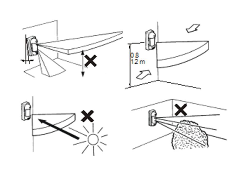
1. Install the detector perpendicular to the ground to have the upper detection area detected parallel to it.
2. Installation height is 0.8 – 1.2 m
3. Mount the detector in such a way that most of the movement area falls within the detection pattern.
4. Too much light such as strong sunlight directly on the sensor may cause an unstable condition. It is highly recommended to avoid this.
To open the detector:
1. Unscrew the lock and remove the top of the case.
2. Unscrew the screws from the back plate. Remove the base plate.
NOTE: never touch the surface of the PIR sensor.
Attach the detector to the desired location. The detector can be placed directly on the wall or used on the post (Ø 43 – 48 mm) using the supplied mounting bracket.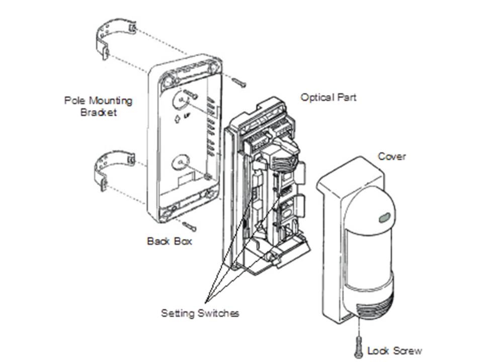
2 Teaching the detector into the receiver
The transmitting module is placed under the optical part of the detector. First study the installation manual of the receiving unit (control panel) to learn how to enter the learn mode. When the receiver is in learning mode, insert the batteries into the detector (polarity is indicated in the detector). The detector will give a learning signal after the batteries have been installed.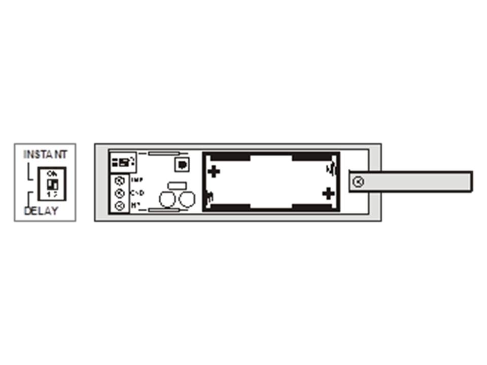
JA-81M transmission module
· Use DIP switch no. 1 to change the system response:
- direct (ON position)
- delayed (position 1).
· Leave DIP switch no. 2 in the ON position.
3 Adjustment
The upper detection area remains parallel to the ground. The lower area moves as shown below depending on the position of the switch. The detection length is therefore limited by the length of the lower detection area, since the upper and lower areas must both be activated at the same time to activate the detector.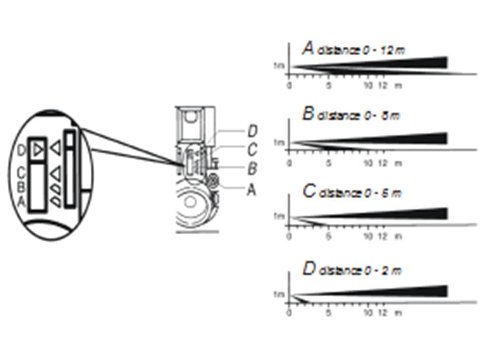
Detection length setting table:
| Position | Max. detection length | |
| Standard | See PLEASE NOTE under table | |
| A | 12 m | 10.0 to 15.0 m |
| b | 8 m | 6.0 to 10.0 m |
| c | 5 m | 4.0 to 5.5 m |
| D | 2 m | 1.5 to 2.5 m |
NOTE: The maximum detection length may vary as above due to environmental temperature conditions.

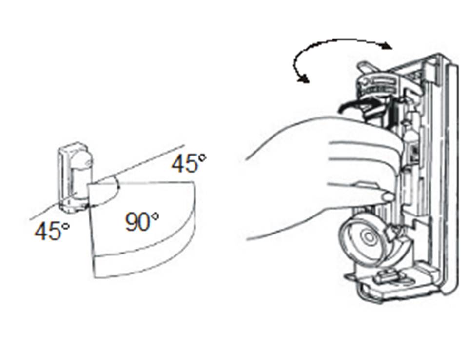
Active area angle is 90°. By holding the pyroelectric unit it can be rotated in the desired direction (in 15° increments).
Demarcate area – the detection area that is exposed to the reflection of sunlight, car light, etc. can be shielded using the supplied shielding plates.
Sensitivity of the PIR sensor can be adjusted at the "SENS" switch in 3 steps:
L - low
M - medium
H - high
Other settings can be changed with a DIP switch:

The LED indicator is used for testing the PIR detector. During normal use it is recommended to turn it off to save batteries.
Depending on the setting of the 120s/5s battery saving timer DIP switch, the motion sensor will be blocked for a period of 5 or 120 seconds after motion is detected or to save batteries.
Depending on the position of the pulse count DIP switch, the detector (above & below detection area) must be activated 2 or 4 times to send an alarm signal.
4 Operation test
Turn on the LED indicator, set the "battery save timer" to 5 seconds and close the detector. Every 5 seconds, any movement in the detection area will be displayed by the LED indicator and the alarm information will be sent to the control panel.
5 Operation
To extend the battery life, it is highly recommended to set the "battery saving time" to 120 seconds and turn off the LED indicator in normal condition. The motion sensor will be shielded for 5 or 120 seconds after detecting a motion. This means that if there is constant movement in the area, the detector will only send this movement information once every 5 or 120 seconds.
6 Test and replace batteries
The detector checks its battery status automatically. If it is necessary to replace the batteries, the detector will inform the system. When battery replacement is displayed, they should be replaced as soon as possible (within one week).
Before replacing the batteries, the receiver (control panel) must be set to the mode that allows the detector to be opened (User or Programming mode).
Use only high quality AAA alkaline batteries for replacement
Please note: Destroy batteries safely depending on the type and local regulations. Although this product does not contain harmful materials, we recommend that you return the product immediately to the factory or seller after use.
7 Troubleshooting
| Problem | Probable cause | Solution |
| Detector gives false alarm | Lower detection area is unnecessarily long. | Set the detection area properly. |
| Detection area receives reflection from the reflector, sunlight, car light, etc. | Remove the reflector, shield the area exposed to the reflection of light or change the position of the detector. | |
| There is a heat source in the area that causes rapid temp. change can cause (oven, stove, etc.) | Remove the source of heat or change the position of the detector | |
| There is a moving object in the area (clothes on the clothesline, plants, etc.) | Remove the moving object or change the position of the detector. | |
| Occasionally no detection | Detection area is not set properly | Set the detection area correctly. |
| Sensitivity is too low | Change the sensitivity to medium (M) or high (H). | |
| Detector not working | Low battery level | Replace the battery |
| LED does not light up | Set the LED switch to ON | |
| LED lights up but no response to the control paneer | The control panel is out of range, check the battery, try moving the detector or the control panel. |
8 Specifications
Power supply 3.6 V - 1 x AA battery Lithium
Battery life approximately 2 years
Frequency 868 MHz
RF strength < 10 mV
Range max. 300 m (open area)
Specification of the Optex VX 402R detector
Detection method Passive infrared
Range 12 m / 90° ; 14 segments
Mounting height 0.8 – 1.2 m
Detection speed 0.3 – 1.5 ms-1
Battery saving timer 5 or 120 seconds
LED indicator only in test mode
Environmental class IV (EN 50131-1)
Operating temperature -20°C to +50°C
Water resistant IP54
Humidity 95%
Dimensions 198 x 80 x 108 mm
Safety level 2 (EN 50131-1)
Can be used according to ERC/REC 70-03